Go to ArticlesKansas City

Assembling the CyberBrick Standard Controller

TutorialAugust 2, 2025

In a previous article, we built the MakerWorld remote-control forklift. Without a controller, it's a very detailed paperweight. This guide assembles the matching CyberBrick Standard Controller.

What to Print

Download the CyberBrick Official Standard Controller from MakerWorld and print the full set. You'll end up with the main housing, a surround, a top cover and top back cover, a bottom back cover, a lever and push-button cover, an access cover, a pair of standoffs, two thumb controls with retainer rings, and two thumb pads. The MakerWorld page includes the official assembly PDF; this post adds the details I wish I'd known the first time through.

Building the Controller

Glue the Parts First

I like to glue a few parts first so they can set while the rest of the assembly is underway. Keep your fingers clear of the super glue.
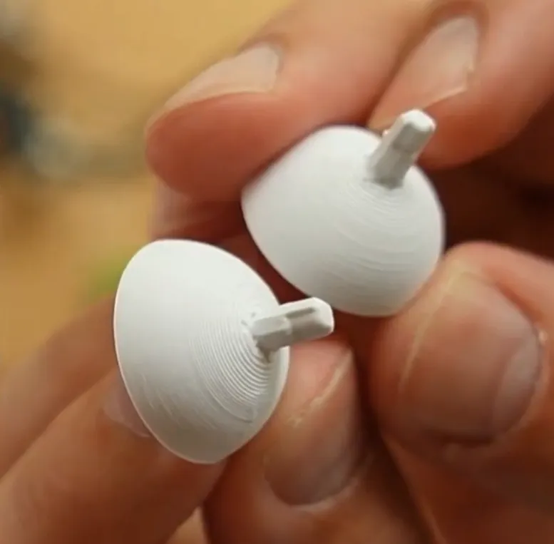
Two small white domed thumb-control caps with square pegs, held between fingertips
Glue the two-piece thumb controls together. A tiny dot of glue on the peg is plenty.
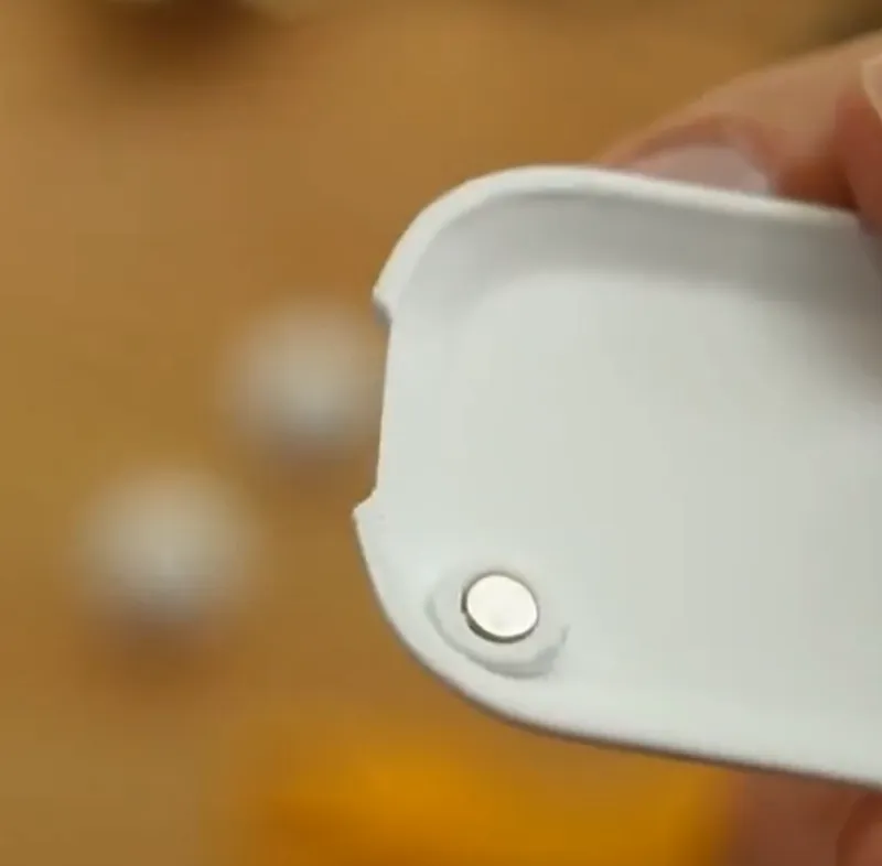
Small round magnet seated in a recess on the inside of the white printed access cover
Place a dot of glue and the magnet in the access cover. Magnet polarity doesn't matter here.
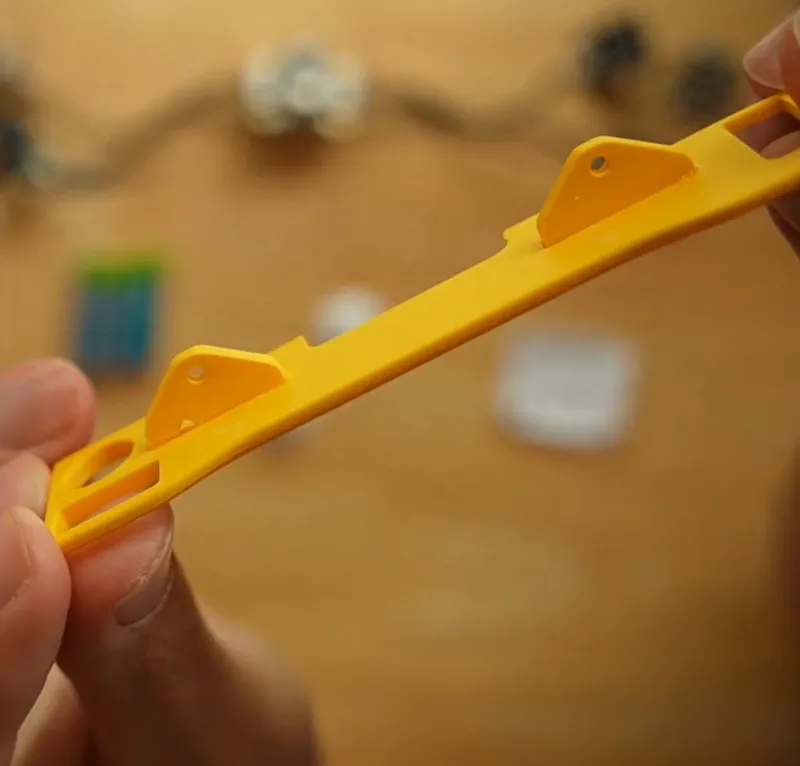
Yellow printed standoff strip with two triangular mounting tabs, held in both hands
Glue the standoffs to the top of the controller. The triangular tabs face up and later carry the electronics.

Wire the Transmitter Module

Follow the wiring diagram to connect the cables and components. The plugs are keyed, so if a connector doesn't fit, turn it around rather than forcing it. The orange wires on one joystick module cross over before connecting; take care not to miss that detail.
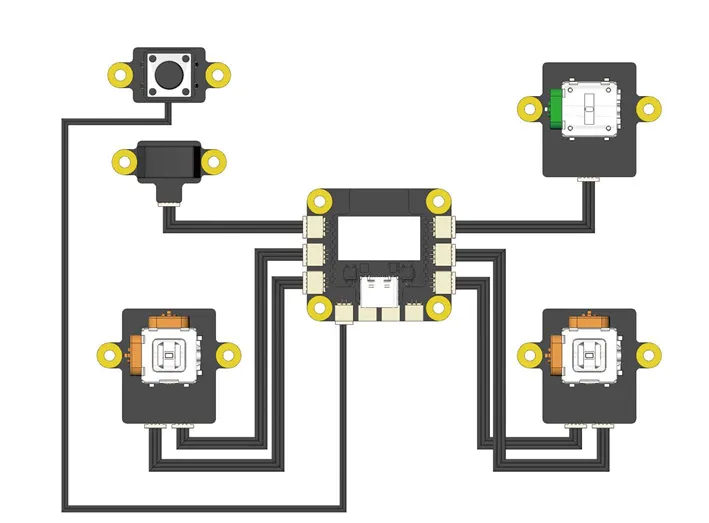
CyberBrick controller wiring diagram showing the transmitter board in the center connected to two joystick modules, a push button, a power switch, and a lever module
The transmitter board sits in the center; both joysticks, the button, the switch, and the lever plug into it. Note the crossed orange wires on one joystick.

Fasten the Electronics

Follow the kit instructions to place and fasten each component onto the standoffs. Check the completed top view before closing the housing; it's much easier to fix a swapped plug now than after the covers are on.
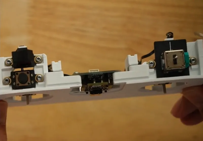
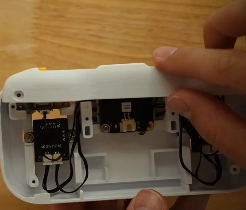
Top-down view of the open controller housing with the push button, transmitter board, and a joystick module screwed in place
Top view with the electronics installed. Button on the left, transmitter in the middle, joysticks at each end.

Close the Controller

Install the remaining printed pieces in this order:

  1. Controller surround
  2. Access cover
  3. Lever and push-button cover
  4. Top cover
  5. Top back cover
  6. Battery-pack wire, then the batteries
  7. Bottom back cover
  8. Thumb controls and retainer rings
  9. Thumb pads
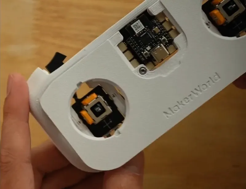
White printed surround fitted over the controller housing, showing the transmitter board's USB-C port and a joystick through the openings
Install the controller surround. The transmitter's USB-C port should line up with the center cutout.
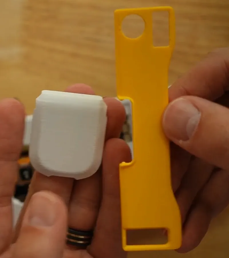
White access cover and yellow top cover held side by side above the controller
Snap the access cover into the top. The magnet you glued earlier is what holds it shut.
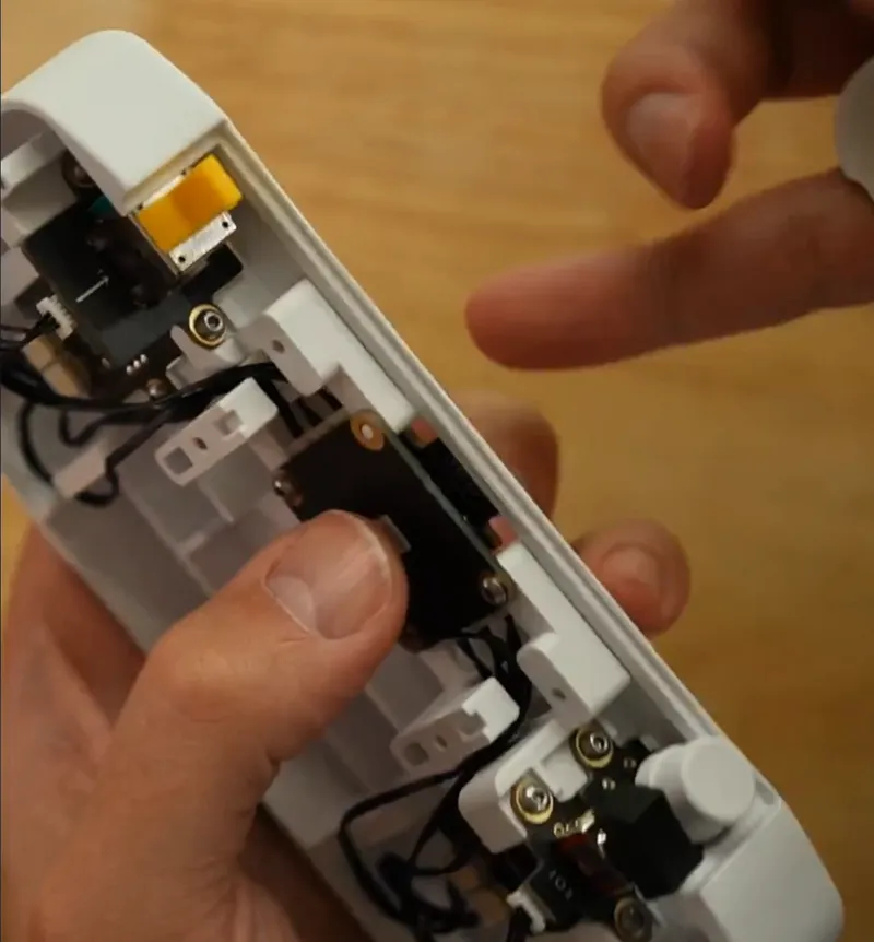
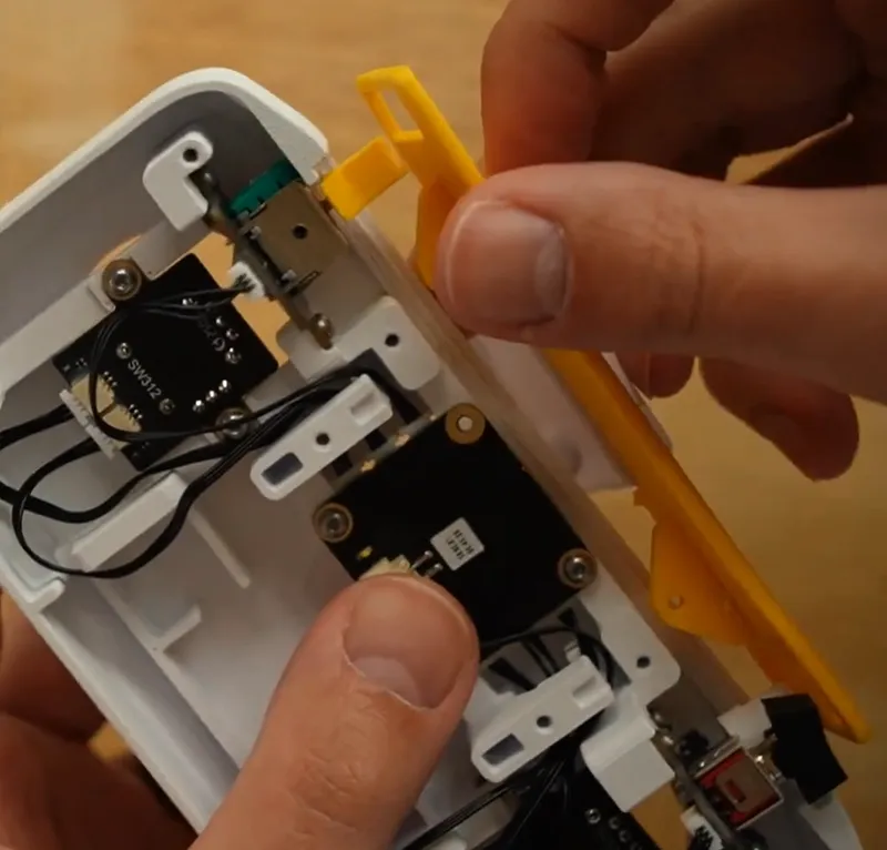
Inside view of the controller with the orange lever module and push button visible at the top edge
Install the lever and push-button cover over the switch and button at the top edge.
Yellow printed top cover being lowered onto the open controller housing
Install the top cover. It drops straight on over the lever and button.
White top back cover pressed onto the controller, with the switch board and battery connector still visible below it
Install the top back cover. The lower half stays open for the battery pack.
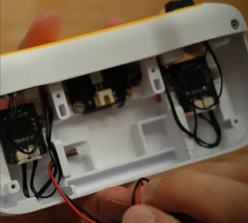
Red and black battery-pack leads routed through the open bottom of the controller to the connector inside
Route the battery-pack leads to the connector, then load three AAA batteries into the pack.
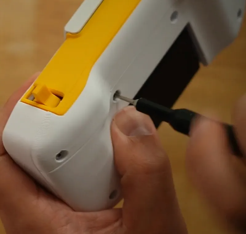
Hex driver tightening a case screw on the back of the controller
Install the bottom back cover and tighten the case screws with the H1.5 hex bit.
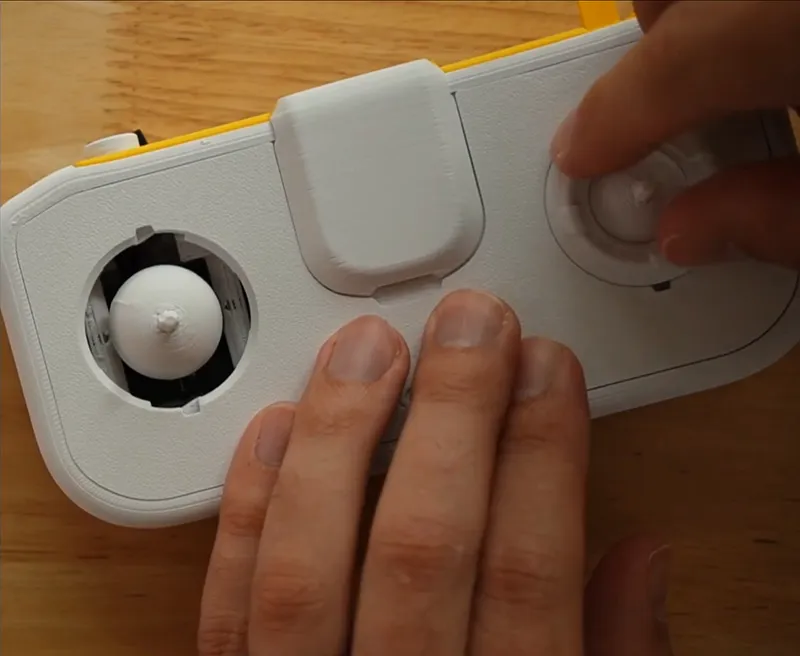
Thumb controls being pressed into the joystick openings on the front of the controller
Install the thumb controls and twist their retainer rings to lock.
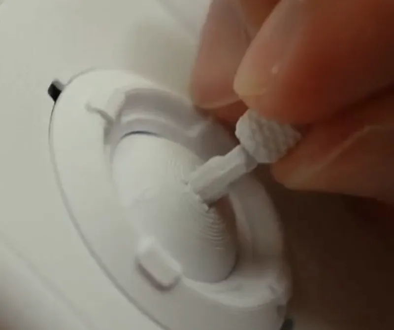
Close-up of a small knurled thumb pad being pressed onto the top of a thumbstick
Press the thumb pads onto the sticks. You're done.

Ready to Drive

The controller is ready for forklift adventures and other CyberBrick vehicles and projects. Builds like this are a good way to move beyond 3D printing alone, and the habits you pick up here, like checking keyed connectors, following a wiring diagram, and test-fitting before closing a case, show up again in bigger electronics projects. Happy building!

Haven't built the forklift yet? Start with the forklift build.